WP1
Irradiations of various crystaline materials have been performed with swift heavy ions at various impact angles. Irradiated materials have been characterized using various analytical methods, including:
- Rutherford Backscattering Spectroscopy in random (RBS) and channeling (RBS/c) modes
- Time-Of-Flight Elastic Recoil Detection Analysis (TOF-ERDA)
- Transmission Electron Microscopy (TEM),
- Atomic Force Microscopy (AFM)
- Grazing Incidence Small Angle X-ray Scattering (GISAXS).
Irradiations at lower energies and characterisation by RBS/c and TOF-ERDA have been performed at the RBI Tandem Accelerator Facility. Irradiations at higher energies have been performed at GANIL. GISAXS measurements have been performed at the Elettra synchrotron facility, Trieste, Italy. AFM measurements have been performed at Univesity Duisburg-Essen and TEM analysis at National Institute of Materials Physics (NIMP), Magurele, Romania.
Illustrative examples of activities
- Dual ion beam chamber for in-situ RBS/c studies
One of the most utilised techniques for indirect measurement of ion tracks is RBS/channelling. However, this ion beam analysis (IBA) technique is not available at large ion accelerator facilities where ion track studies are mostly done. Recent commissioning of the dual ion beam chamber at the RBI, Zagreb opened up an opportunity to study kinetics of ion track formation using in-situ RBS/c. Ion track formation can be accomplished using swift heavy ions delivered by the 6 MV EN Tandem Van de Graaff accelerator, while simultaneously RBS/c measurement can be done using proton and lithium beams delivered from the 1 MV Tandetron.
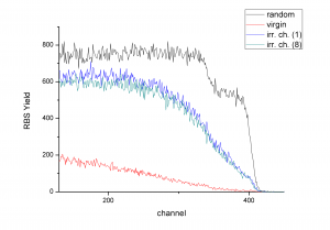
As a feasibility test, we have investigated rutile TiO2 single crystal (Crystec) irradiated previously at IRRSUD beamline (GANIL) with 92 MeV Xe23+ up to a fluence of 1012 cm-2. Multiple RBS/c measurements on the same position did not affect observed defect distribution.
- Monitoring stoichiometry changes using ERDA
Another approach for in-situ IBA is to use swift heavy ions for simultaneous material modification and monitoring using ERDA. As shown recently (2) monitoring elemental changes in the sample, ion track characterisation can be accomplished. Here we present two examples.
- monitoring stoichiometry changes during ion track formation in GaN
Wurzite GaN thin films were irradiated at RBI, Zagreb using 23 MeV I6+. Surface modifications were investigated by both tapping and contact mode AFM (UDE). After grazing incidence irradiation, chainlike surface ion tracks consisting only of nanoholes were observed. To investigate possible stoichiometric changes of the GaN, in situ TOF-ERDA measurements were performed at the RBI using a 23 MeV I6+ beam at 20° and 1° grazing angle of incidence with respect to the sample surface. In contrast to 20° measurement, the offline analysis of the TOF-ERDA measurement performed using 23 MeV I6+ at a grazing incidence angle of 1° shows a significant loss of nitrogen from the first 8.5 nm already at the fluence of 2×10¹¹/cm2.
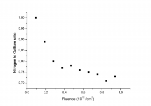
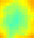
Nitrogen-to Gallium ratio calculated from an offline analysis of in-situ TOF-ERDA measurements (23 MeV I6+, Q = 1°)
- monitoring hydrogen loss from amorphous Al2O3 film
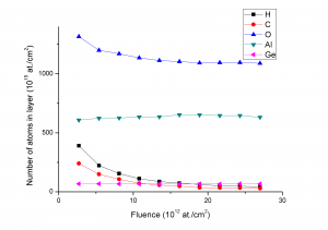
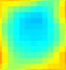
Results of ToF-ERDA (16 MeV I, Q = 20°)

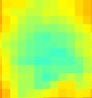
Results of ToF-ERDA (23 MeV I, Q = 20°)
As a second example of in situ ERDA, we have monitored hydrogen loss from amorphous Al2O3 film. Assuming cyllindrical geometry of ion track and applying Poisson law, ion track radii around 1 nm were estimated. Ion tracks after 23 MeV I irradiation have 15% larger track radius than tracks formed after 16 MeV I irradiation.
More about the scientific output within WP1 can be found under ‘Publications’
WP2
Irradiations of diamond crystals with carbon ions, tungsten and tungsten alloy with iodine, tungsten and helium ions have been performed at the RBI Tandem Accelerator Facility as well as RBS and RBS/c analysis of virgin and implanted diamond samples. The work related to irradiation of tungsten and tungsted alloy have been prformed in collaboration with the Culham Center for Fusion Energy (CCFE).
Illustrative examples of activities
- Ion irradiation and angular scanning of W(100) crystal
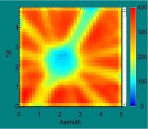
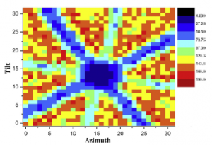
We demonstrate a possibility to apply RBS/c for studying of damage in crystalline W(100) tungsten induced by ion beam irradiation. The tungsten monocrystal sample was irradiated by 5 MeV O+2 ions at the Dual Beam Ion Irradiation end-station. It has been demonstrated that damage (amorphisation, atomic dislocations) in tungsten crystal can be monitored by angular scans near the channel. Deterioration of the channel due to irradiation is visible at two-dimensional angular scans.
a) b) c) d)
a)Two-dimensional angular scan of W(100) crystal before irradiation. Central parts of two-dimensional angular scans of W(100) crystal in the angular range of 20x20 around the channel shown for comparison: a) before irradiation (intact crystal); b) after 1h iradiation; c) after 2h irradiation.

One dimensional normalised angular scans of W(100) crystal over the channel:
a) black – before irradiation; b) red – after 1h iradiation; c) green – after 2h irradiation.
- Proton backscatteing in channeling mode from a diamond crystal
Proton backscattering spectra from monocrystal diamond were collected for various proton energies below and above the strong resonance of the 12C(p,p0)12C elastic scattering at 1737 keV.
The samples were aligned along the <100> channel before the collection of spectra. The channel is clearly visible.
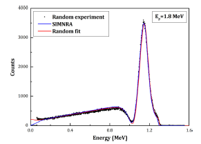
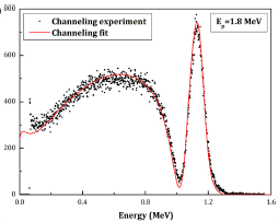
Left) Backscattering spectrum for 1.8 MeV protons impinging on a randomly oriented diamond crystal, related SIMNRA simulated spectrum and the corresponding computer simulated spectrum by the computer program code CSIM developed at the Laboratory of Physics, Vinča Institute of Nuclear Sciences. Right) Backscattering channeling spectrum for 1.8 MeV protons impinging on a <100> oriented diamond crystal with computer simulated spectrum by the computer program code CSIM. More details can be found in M. Erich et al, NIMB381(2016)96.
More about the scientific output within WP2 can be found under ‘Publications’
WP3
Charge collection efficiency studies have been performed using focused ion beams at the Ion Microprobe installed at the RBI Tandem Accelerator Centre by Ion Beam Induced Current (IBIC) and Time Resolved IBIC (or TRIBIC) techniques. At the same time magnetic quadrupole triplet has been designed, constructed and tested for installation at the ‘dual-beam’ end-station. It is planned to test IBIC with focused beams at the ‘dual-beam’ end station with combined ion beam irradiation from the other accelerator.
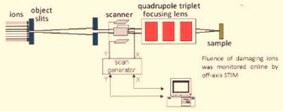
Schematic presentation of using focused ion beams for selective damaging of small detector areas.
Illustrative examples of activities
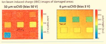
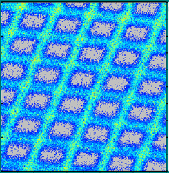
- radiation hardness of scCVD diamond
Diamond is considered to be a radiation hard material that should replace conventional detector materials in radiation intensive environments. Radiation hardness studies on diamond detectors are usually exploring the charge or current signal reduction of a particular detector after exposing it to some fluence of accelerated particles. The figure below shows ion beam induced charge (IBIC) images of damaged areas on one detector: (left on 50 µm sc CVD, and right on 6 µm sc CVD).
- in-air ion beam charge collection efficiency studies with focused ion beams
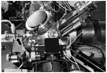
Most of the work on the subject on Charge collection efficiency have been performed using focused ion beams at the Ion Microprobe in vacuum. Recently we upgraded the system to enable performing irradiations in air. The figure shows a side view of the RBI microprobe experimental setup. A quadrupole triplet lens is positioned on the right side of the spherical scattering chamber. Arrow (on left) indicates the position of the in-air microbeam focus with CMS pixel readout chip mounted for IBIC tests.
- charge collection efficiency studies at the dual beam end station
Simultaneous irradiation of semiconductor materials (e.g. Si, SiC and diamond) by dual beam could be used to explore capabilities for in situ study of kinematics of radiation-induced defects. In our setup it was planned that the ion beam from the 6.0 MV tandem would be used as a damaging beam, while the second beam from 1.0 MV tandem would be used for the measurement of charge transport degradation using IBIC technique (probing beam).
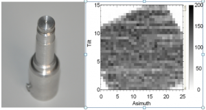
At first, a feasibility study was performed to check for a possibility probing ion beams collimated to 25 mm using a circular collimator developed for the use in electron microscope. The figure shows such a collimator setup and the 2D image of a virgin Hamamatsu diode obtained by 2 MeV protons (scan size was 4 x 4 mm). Although in principle we demonstrated a possiblity to perform IBIC scan by collimated probing beam, we decided to develop dedicated magnetic focusing lenses to be installed at the dual beam end station in order to use focusing probing beam.
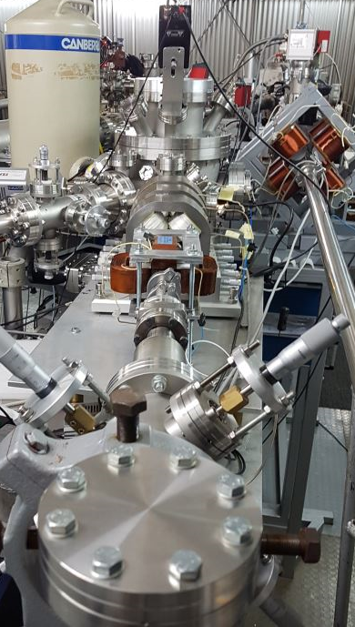
In house designed quadrupole magnetic triplet has been produced localy and installed at the beam-line from 1.0 MV tandem. New chamber has also been designed and installed to enable measurements of RBS-RBSc, PIXE-PIXEc, PIGE, NRA, IBIC, IBIL measurements. The old channeling end station has been installed at another beam line. The focusing-scanning system has been tested and good capabilities to perform ion microbeam measurements have been demonstrated.
MESH1000, 25.4 µm
More about the scientific output within WP3 can be found under ‘Publications’